
Monday:
We began work on our PCB. We tested our breadboard circuit and it worked perfectly. In order to clean up the circuit and make it easier to store in the chassis, we decided to move on to a PCB. This required a lot of time: we started off by trying to print the PCB on the OEDK PCB mill. However, the milling would have taken three hours so we decided to try using etching chemicals. This should have taken a small amount of time but we could not get the board design to imprint on the copper board.
Tuesday:
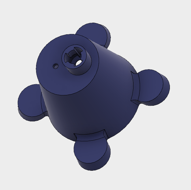
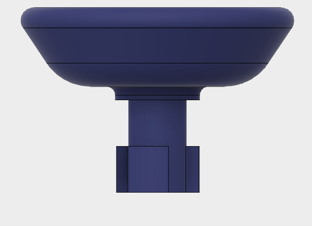
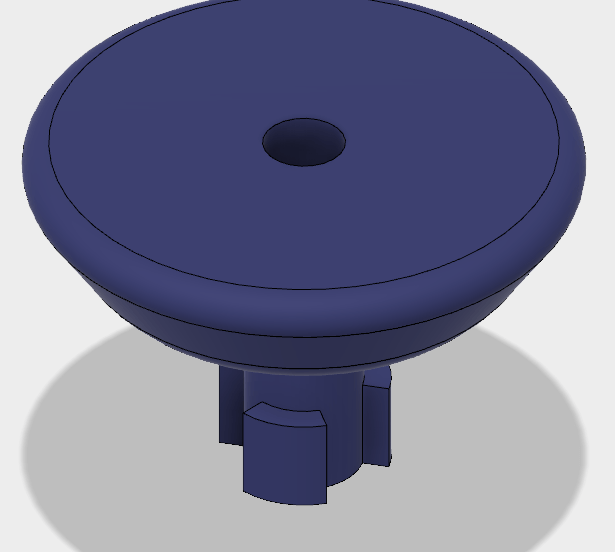
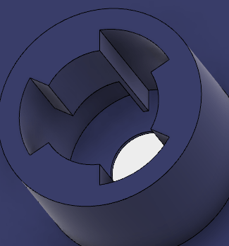
We created a new cap for the device. This cap built on the latch mechanism of the previous design but added a locking mechanism so that it would be impossible for the tube to get tied up on something and pop out. This was a suggestion of our client Dr. Abadi. We were initially reluctant to adopt this design because we knew that 3D printers could not produce threading with which to lock two parts together. However, we realized that by adding a gap between the top and bottom of the latch mechanism, we could insert the tube top and secure it into place.
Since the PCB took a lot of time to develop, we decided to build a perf-board on the side. This was just in case the PCB could not be built in time for the final prototype. A perf-board would still involve using some wires, but it would be cleaner than the breadboard design. However, in the end, we managed to etch the PCB and verify that it worked.
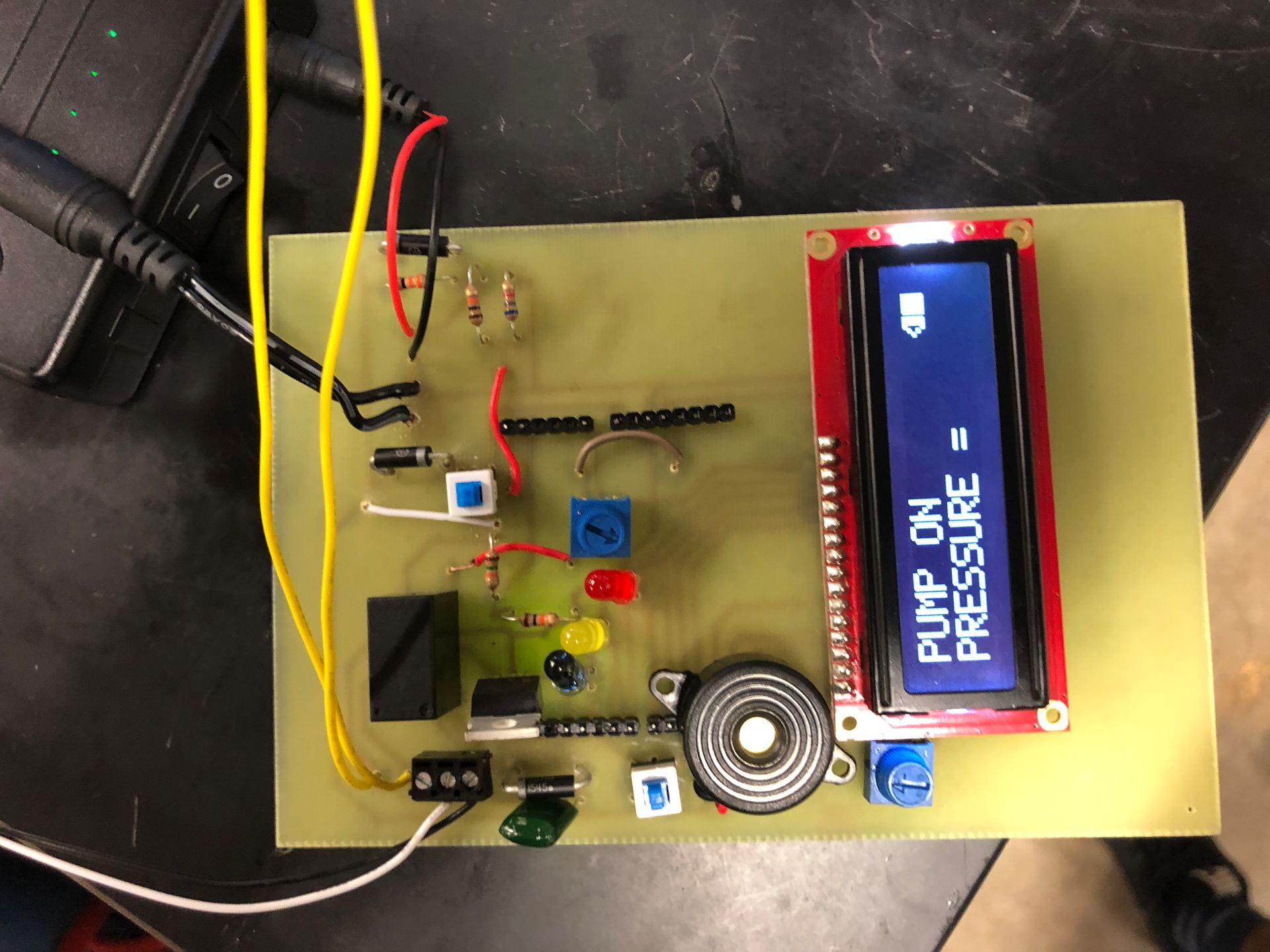
PCB
Wednesday:
A lot of our materials arrived! We received our float sensor (this was to replace the exposed wires in the reservoir) and our pressure sensor. The float sensor worked like expected, however, we could not attach the pressure sensor to our tubing. We decided to order a new sensor that had threading that would allow us to connect it to our tubing. This new sensor also worked in a range of pressures that was closer to the ones we were operating in (0-1atm). Since this pressure sensor outputs a small signal (70mV to 130mV) so we also looked for a differential amplifier with which to read the signal accurately. This required an extensive amount of research and took up a significant portion of the day.
We also began the testing stage by summing up the materials cost of our device and comparing it to our design criteria. Our device is under $200 so it passed!
Thursday:
Our PCB was complete, however, we realized that we would need to separate the LCD and LEDs from the rest of the board. This would allow us to insert the LCD/LED on the top of the lunchbox and thus make the design more discrete. We designed and printed this new board but are yet to test it.
The cap also required some redesign. We realized that the mold we made on Tuesday was not very successful: the walls were very thin and we were unable to insert the bottom component of the mold into the cap. As a result, we decided to make a new mold: this one allowed us to verify that the mold had been inserted properly into the cap and had wider walls for the cap.
We also carried out testing throughout the day. We gathered user feedback on our alarm system, and measured the sound level of our pump. Our pump came in under 40dB so it passed. We have not finished gathering feedback on the alarm system but we are pretty close.
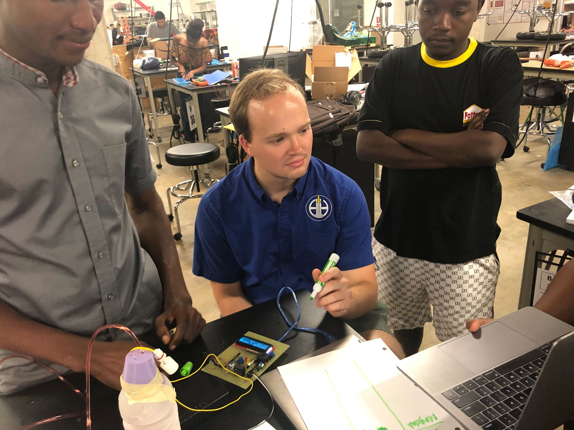
Alarm testing
It sounds as if you are making good progress. However, though your pump passed one test, Harrell is still interested in what vacuum in millimeters it is pulling.
You write very clearly and effectively about your work.
Thanks! We are yet to do any thorough testing on the pump pressure, however, after attaching the pump directly to our old pressure sensor we got a gauge pressure of -750mmHg. We are not sure how that will compare to the gauge pressure when we have 3ft of tubing separating the tube from the wound site but we are eager to check it out.