
Team Gotta Cast ‘Em All is back in the OEDK this week to continue developing our casting stand for Hanger Clinic. This week has been a busy week refining the design of our casting stand.
To better understand the size constraints of our device, we developed a low fidelity flat prototype with the max dimension of our device. This prototype was made out of cardboard the size of 62″ by 30″. Caster wheels were attached by duct tape to the bottom of the cardboard so that we could move the prototype around the OEDK. After testing with this prototype, we determined that 62″ in length is too long for our device. We determined that the optimal length of our device when moving it should be around 42″. After determining this dimension, we decided to review the other dimension of our design to figure out how to move forward. We decided that for our device to be 42″ in length when transporting, we would make the armrests telescoping so that they could be extended while the device is being used to allow enough space for the prosthetist and retracted to a smaller length when being transported and stored.
After calculating these new dimensions, we made a full sketch of our device to figure out all of the connections and components before we began creating our CAD model. Some of the design considerations while we made the full sketch of our design include how wheels would be attached, how the height and armrest width would adjust, and which materials to use. The front wheels supporting the armrest vertical supports will be dolly wheels, which is a based that incorporates three small wheels. The vertical backrest support will have a ‘T’ shaped base with three total locking caster wheels attached to it. We are planning to use square telescoping tubing with pre-drilled holes to allow our device to easily be raised and lowered to accommodate patients of all sizes. Weld-in pins will be utilized to lock the height and width adjustment in place.
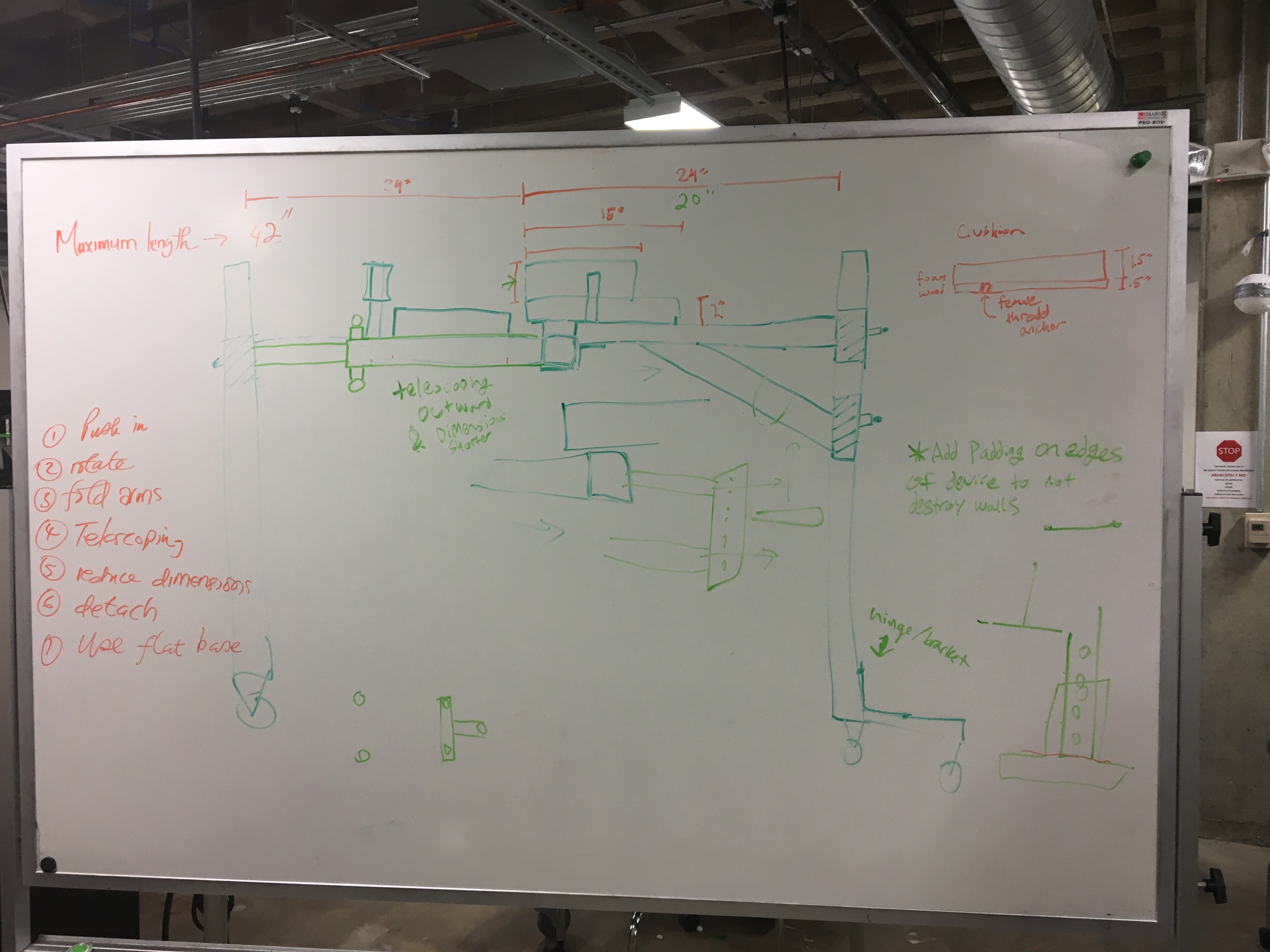
Deciding device dimensions
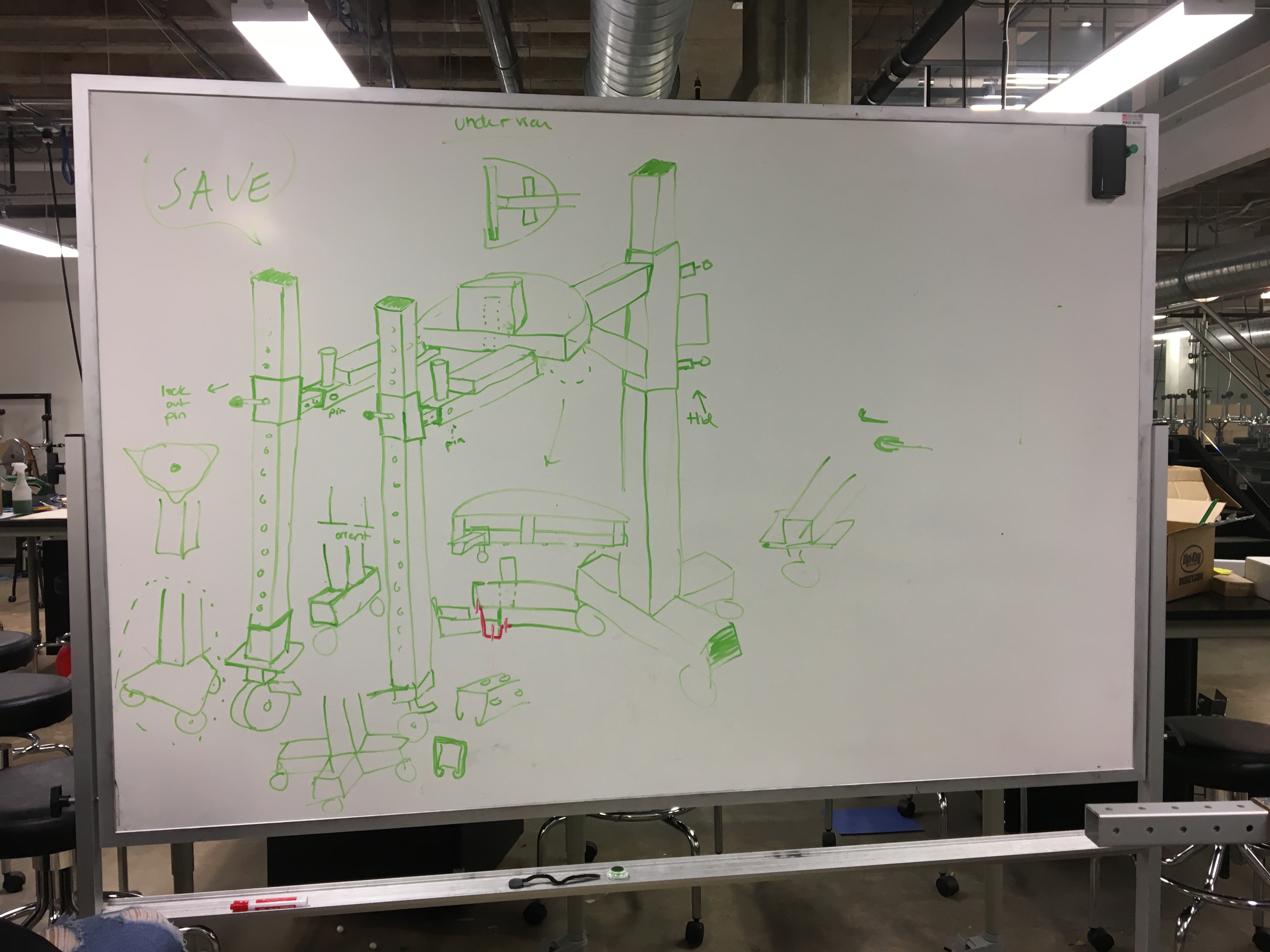
Sketch of the design of our casting stand
At the end of last Friday, Liz and Tori taught Blessings and I how to sew. Because constructing our device will incorporate a lot of sewing, it is very valuable to learn this skill. Liz was able to create high quality cushions using vinyl and foam found at the OEDK.
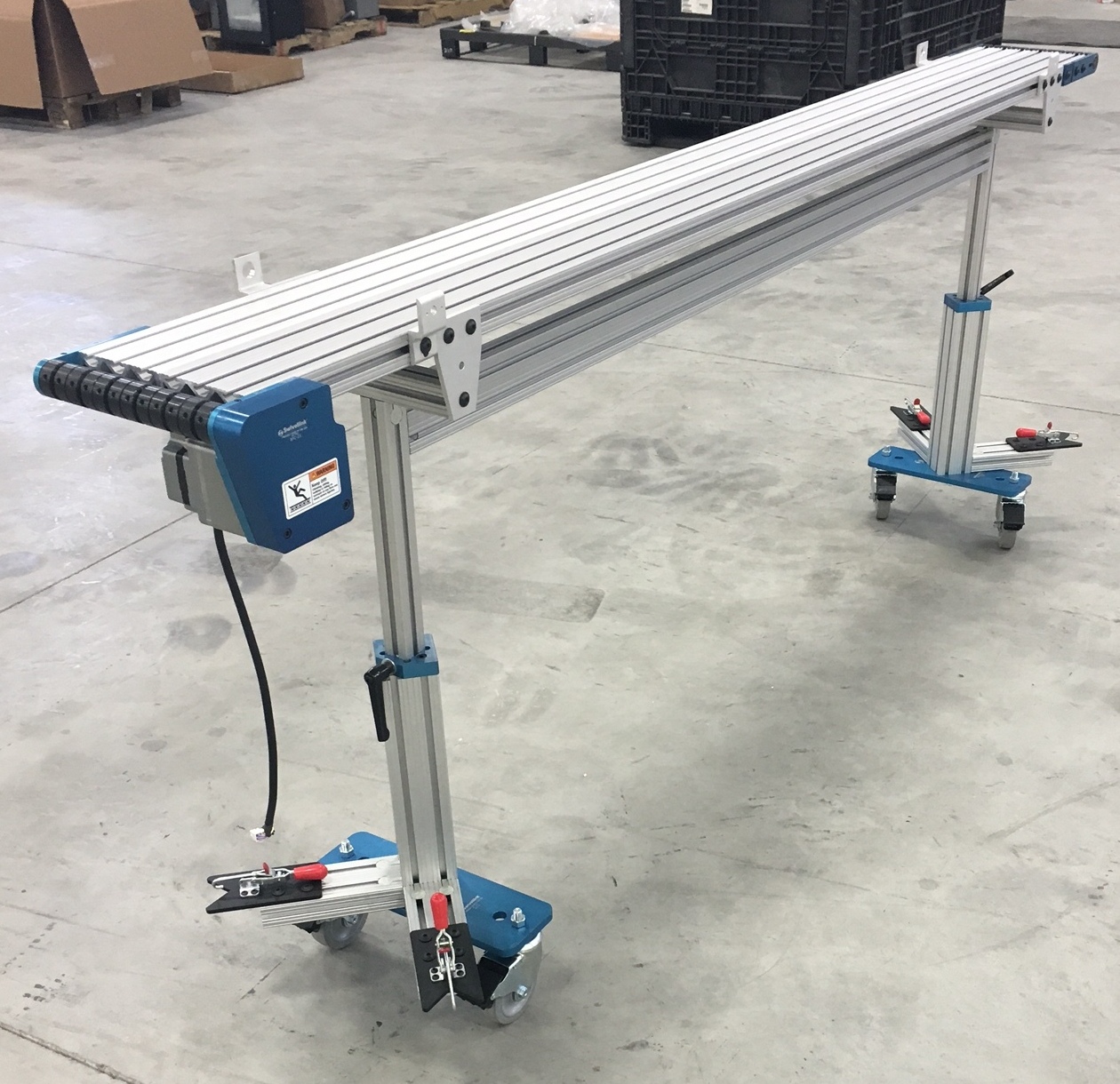
We began Monday with a team pit stop to evaluate our team’s dynamics and progress. While I have been overall happy with my team’s effort, it was helpful to discuss any issues that we encountered and determine ways to improve our team. Later in the day, our team took a trip to Home Depot, Michaels, and Joann’s Fabric to search for materials and determine prices. During our visit to Home Depot, we spotted a portable scaffold that incorporated many components that would be featured in our device. The bottom of the scaffold had casters bolted into square tubing. At the top, the scaffold could raise and lower as a result of two pins from a U-bolt holding it in place. This U-bolt was secured by a bracket and could move in and out of the tubing due to a spring. At Michaels and Joann’s Fabric, we found various foam and vinyl that we could use for our device.
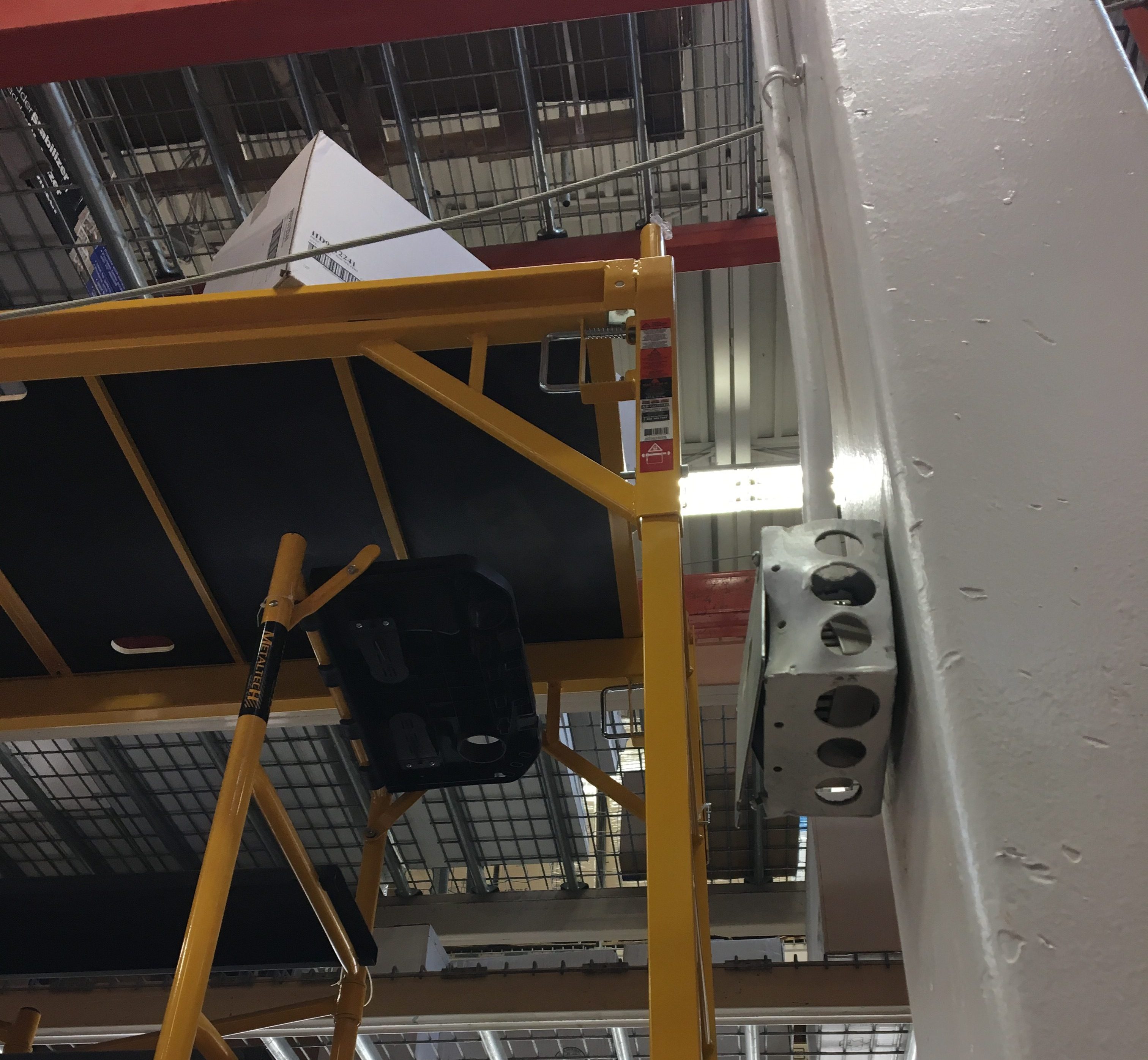
Handle spring latch on scaffolding at Home Depot
After returning from these stores, we began constructing a medium fidelity at the same scale of our design. We decided to use PVC as the material for this prototype since it is readily available in the OEDK and there are many size pieces of PVC that would allow telescoping between a smaller piece and a larger piece. On Monday we began cutting the PVC to the appropriate lengths and finished constructing the prototype on Tuesday. Tori created the shapes of the cushions out of laser cut wood so that we could visualize how the cushions would attach to our structure. Unfortunately, after a failed attempt to use epoxy to fasten the laser cut wood cushions to the PVC, we resorted to using duct tape to adhere the wood to the PVC. Though, once all the connections had been secured with duct tape, our device failed to stand by itself. Because it was not stable, we added extra PVC components to increase its stability. While this therefore limited the scope of the medium/low fidelity prototype as it was no longer adjustable, we could still use it as a model for visualizing the dimensions of our device and testing its portability.
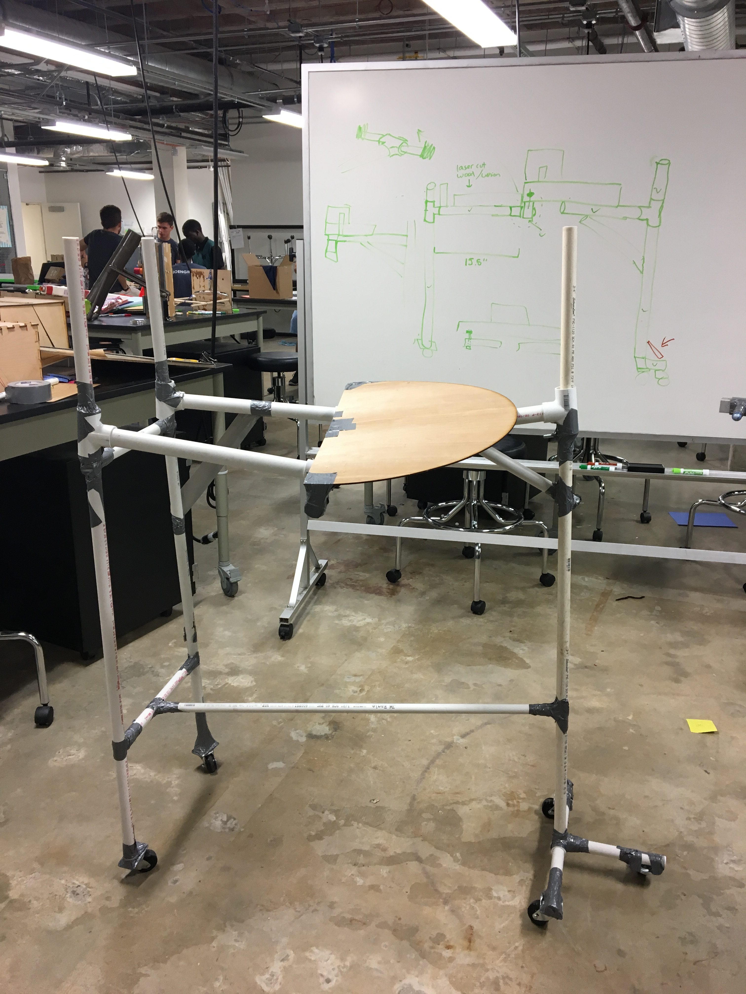
Medium fidelity prototype
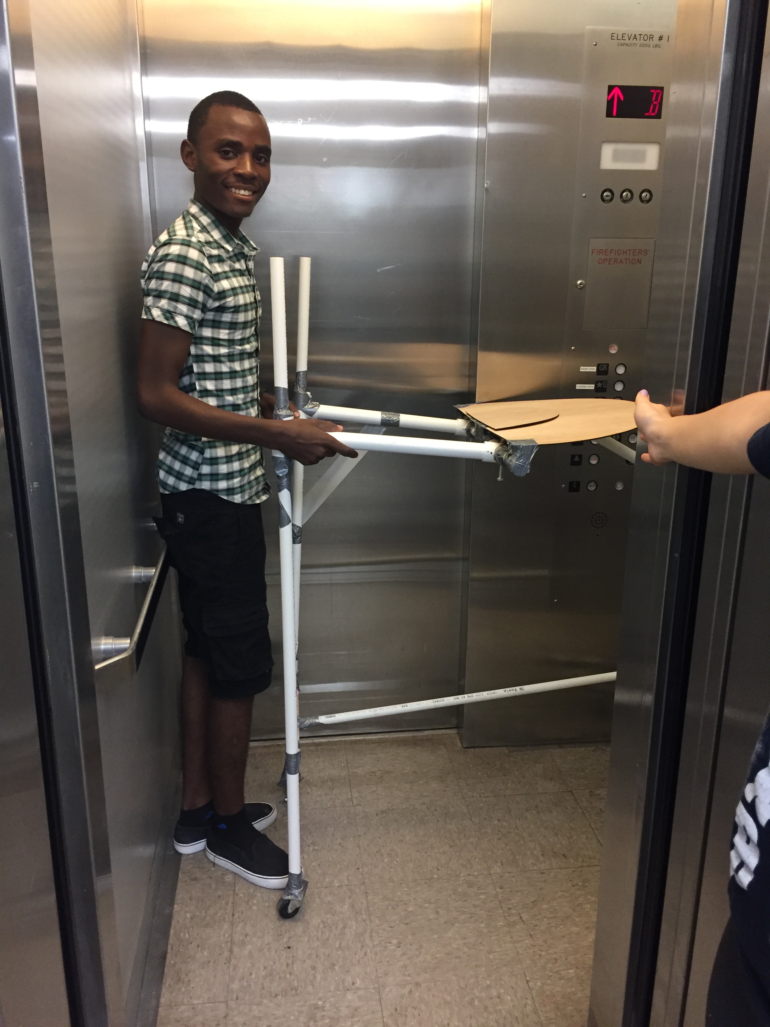
Blessings transporting our medium fidelity prototype to the elevator
Once the medium fidelity prototype was constructed and the full sketch of our device was drawn, we began determining which materials to order. This involved searching McMaster Carr, Home Depot, Joann’s Fabric, and various other suppliers to look for the components that we would need in to construct our device. Thanks to our visit to Home Depot, we decided to construct a handle spring latch to serve as two pins to hold the height of the device in place that can be moved through a handle made out of a U-bolt. To fully realize this design, we laser cut a box and added a U-bolt, spring, and some bolts that we found lying around the OEDK. This enabled us to understand how the mechanism could be incorporated into our design.
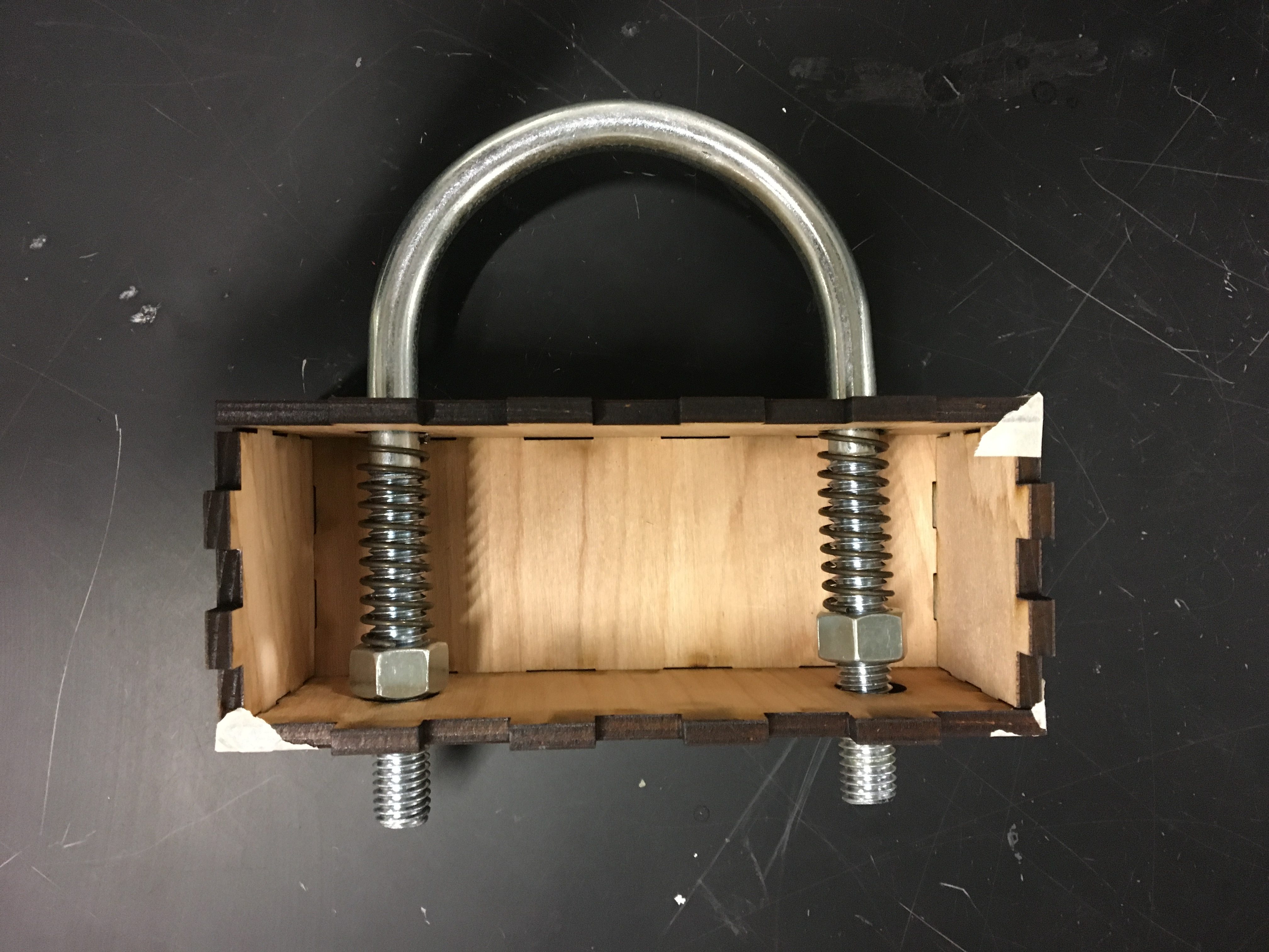
Spring latch made with a U-bolt
Now that most of our materials are determined, we were ready to begin designing our device in SolidWorks and creating designs of the patterns for the vinyl, foam, and upholstery. Liz and Tori started creating the patterns for the cushions while Blessings and I began designing the CAD model of the casting stand in SolidWorks. By the end of the day, we were able to have the basic structure of the square tubes complete. Though, after talking with Dr. Wettergreen at the end of the day, we were suggested to look into use aluminum telescoping tubes rather than steel. The advantages of aluminum over steel include its lightweight and nicer finish. Since the wheelchair transfer project team were also in need of telescoping tubing, Dr. Wettergreen suggested to both of our teams to consider products that feature telescoping aluminum tubes, such as crutches, and search for the aluminum suppliers for the crutches manufacturers. The next day, we began searching for aluminum square telescoping tubes with pre-drilled holes. Since we found these telescoping tubes made out of steel on McMaster Carr, surely there would be a similar product made out of aluminum instead of steel. Unfortunately, we could find no such product on McMaster Carr, 80/20, Unistrut, or any of the other companies that we searched. After discussing our lack of success with Dr. Wettergreen, he urged again to continue searching for aluminum telescoping tubing. He advised to call McMaster Carr and 80/20 to talk to technical support to figure out if they know of any products corresponding to what we were searching for and if they had any suggestions for us. After calling McMaster Carr and 80/20, I was told that they do not produce the type of product that I described. However, 80/20 fortunately recommended me to contact Houston’s local manufacturer of 80/20, Hartfiel Automation and Shepherd Controls, to hear their recommendations and possibly see if what out team needs could be custom ordered. After leaving a voicemail after two call transfers and receiving a call back later in the day, I was directed to a company called Swivellink, which produces uniquely design accessories for 80/20 aluminum extrusions. Specifically, I was informed of a product that makes two pieces of 80/20 capable of telescoping. This product is actually very cool, and if 80/20 aluminum extrusion were used in our design, our device would look very nice. However, once I constructed a price estimate for the costs of steel telescoping tubing and the 80/20 extrusions and Swivellink product, I found out that going with the 80/20 option would cost twice as much as using steel. While we have not made a definite decision on the structural material, we are likely going to continue with a steel frame unless we find any other product that we could use.
Swivellink telescoping technology with 80/20 aluminum extrusion example [photo from swivellink.com]

Current version of casting stand using a steel telescoping frame (isometric view)
Current version of casting stand using a steel telescoping frame (rear corner view)
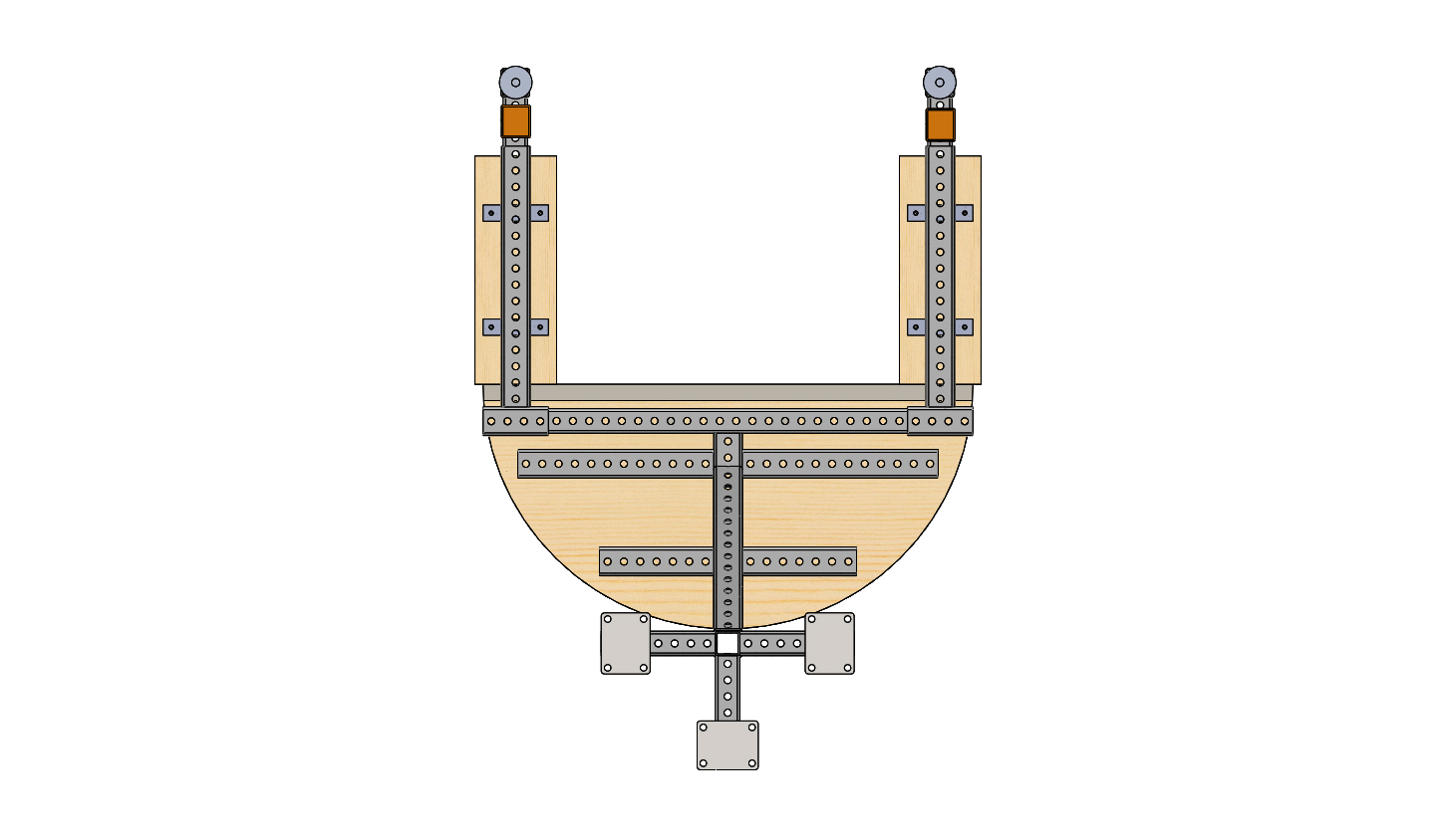
Current version of casting stand using a steel telescoping frame (bottom view)
You detail well the many problems your team has encountered.
I find your postings and oral explanations thorough and well worded.