This week, we delve deep into prototyping.
Having finished reconstructing the previous team’s prototype, we were ready to move on to developing our own device.
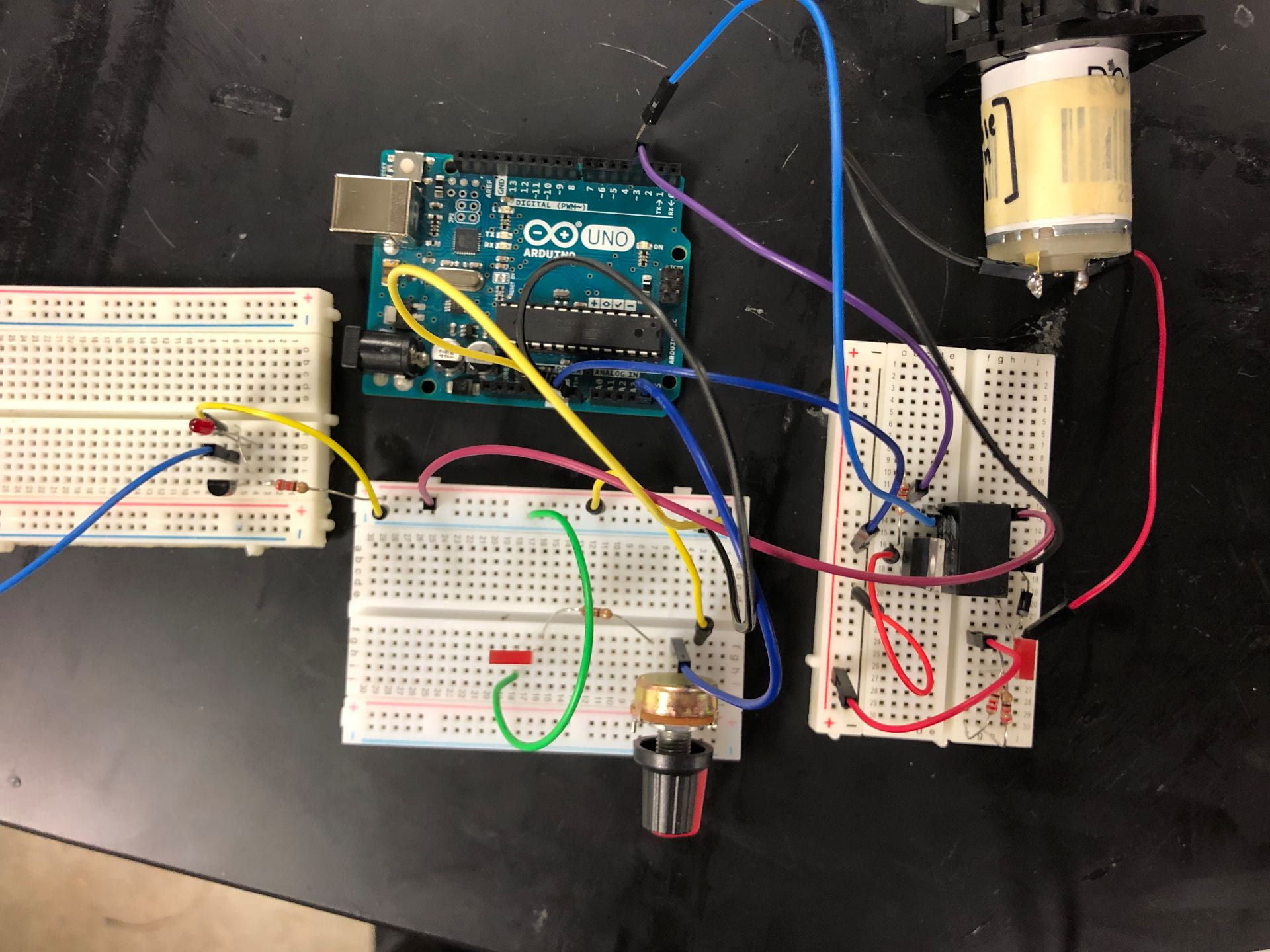
We had developed a circuit diagram that showed the various electronic components of our circuit. We broke up this diagram into its main component sections and divided them among ourselves. This allowed us to make progress on various fronts and not have to run into the problems one usually encounters when integrating many parts at once. The main parts we were on were: controlling the pump, displaying information on the LCD screen, and creating an alarm system for when the reservoir was filled or the pressure was outside the desired range.
All of this required many hours of debugging, research into arduino code, and of course…breadboards.
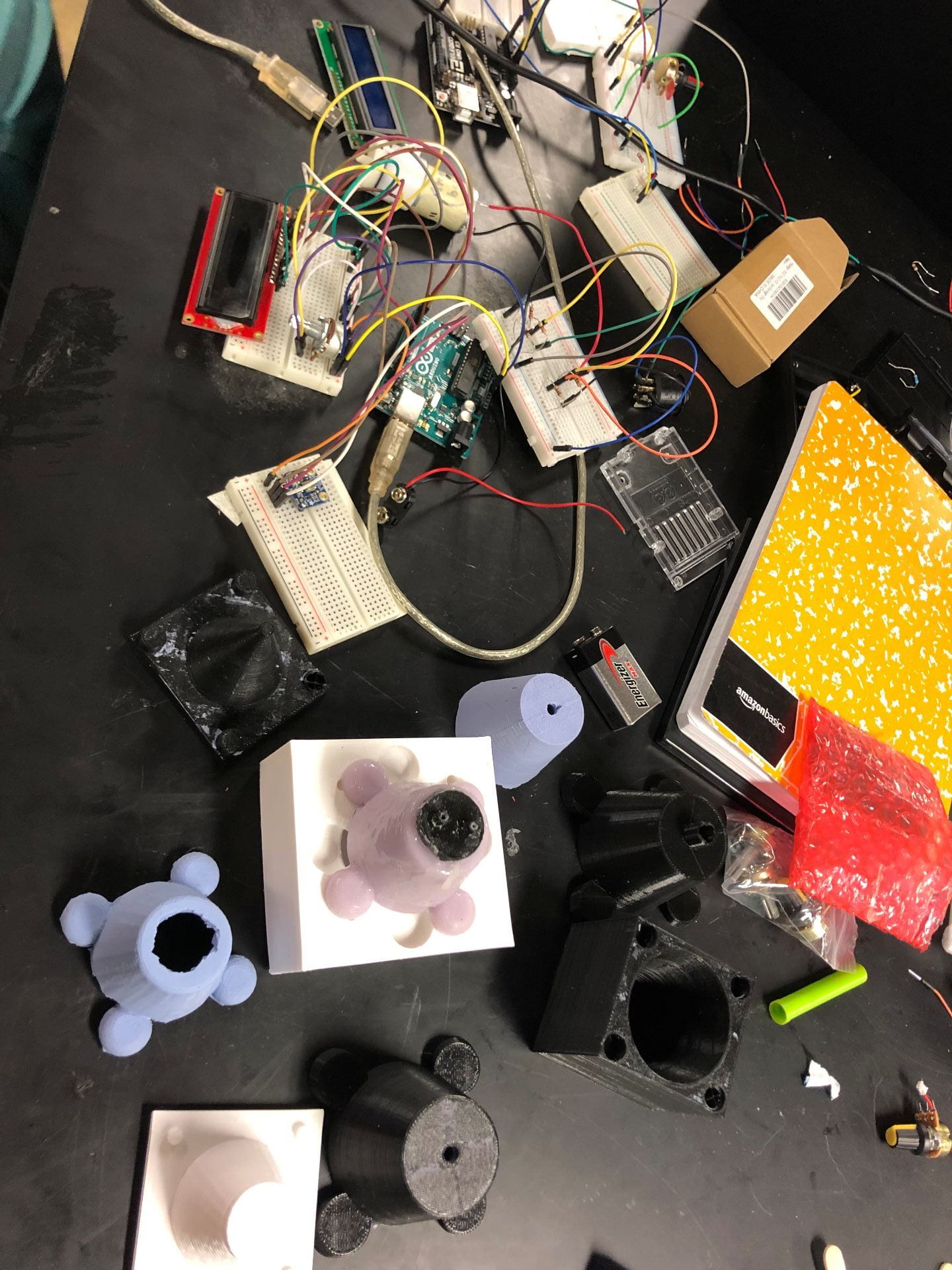
Our work table after this week
Despite this, we all learned a lot about arduino programming and the functions of circuit elements. For example, although I was familiar with potentiometers, motors, and LEDs I had never worked with transistors or relays before. It was interesting to figure out how they operated and how they could be used in various applications.
After we each finished our section, we came together to integrate the various parts we were all working on. We finalized this today. However, before we can move on to a higher fidelity circuit (a PCB) we still need to implement new buzzers (the one’s we currently have do not produce enough sound), find a rechargeable battery that can power our circuit, add battery life estimates, and a recharge feature.
On the side, we began thinking about ways to test the pressure generated by the pump, and brainstormed various options for determining whether the reservoir is full or not. We decided to use a float sensor as the idea with the exposed wires made our client uncomfortable. We also 3D printed, and improved our current cap design. We added a locking mechanism to the cap so that the tube would be secured into place as soon as it was connected to the reservoir.
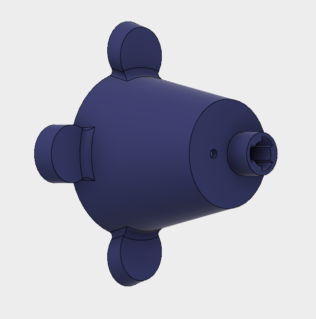
New cap with fancy fillets
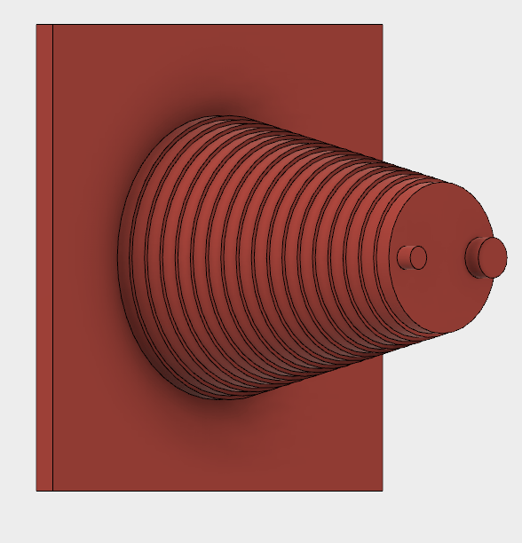
New cap mold
We also decided to make another cap mold. We decided to put ridges on this one just so that we could test whether having the ridges allowed the cap to better stick onto the top of the reservoir. Developing these CAD models helped me refine my CAD software skills, I had not worked in Fusion360 for a while and getting to work on the various cap designs really helped me identify how to most efficiently build objects and add features. I am by no means an expert (AutoCAD still scares me a bit to be honest) but I feel like my understanding of CAD software has definitely improved.
We still have a long way to go, after finishing our circuit, we still need to assemble it into the chassis and test extensively. The long term testing will help us identify all of the remaining shortcomings of our design and hopefully pave the way for a final product.
You may feel uncertain about AutoCAD now, but you are obviously learning a great deal. Your work table looks so complex, but you are making order out of apparent chaos.