I can’t believe we’ve been in it for 5 weeks. After our mid-presentation last week, we realized we had much more to do and began to ramp up the speed. We very carefully just finished assembling 2 working prototypes! We extended the battery holders to a breadboard and a fuse holder, and get very stable readings when we apply oxygen. We are very excited to begin true user testing of the product tomorrow by going to sunbelt medical and getting feedback from Sunny – A very helpful man that owns a medical equipment company in Houston.

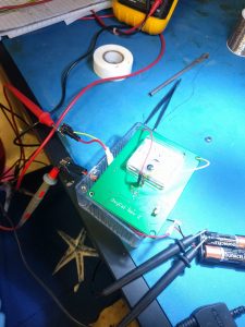
Working prototype I built with extended battery holders to a breadboard
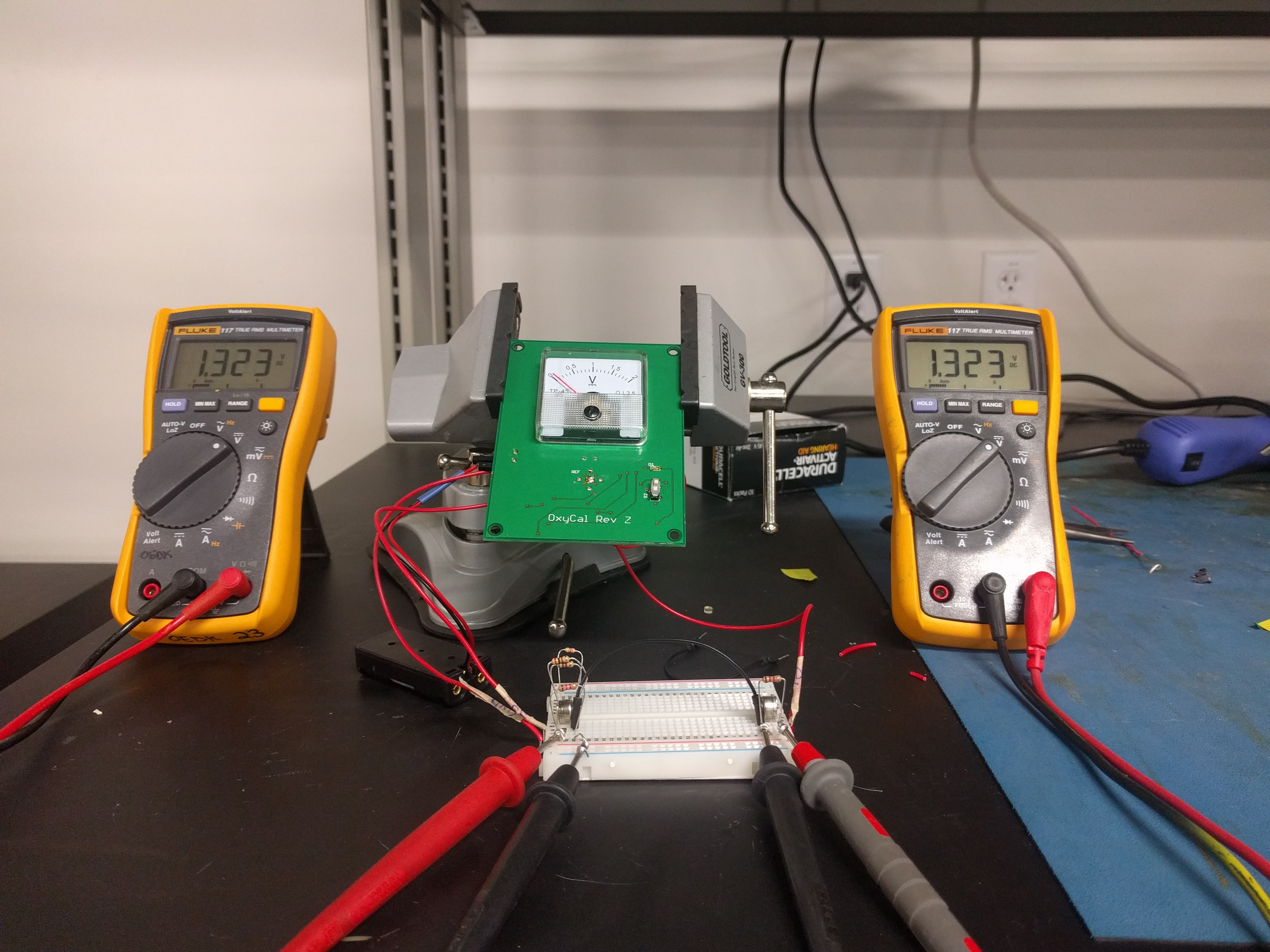
Tiwonge and Charity’s working prototype
Carlos has been working with the digital circuit as well. He ordered parts today for a surface mounted chip that resembles that of the TI MSP 430 controller that he’s been prototyping with. The work looks promising, and it might be possible to have a working digital circuit by the end of the program, ready for fabrication.
Our problems
We’ve had a lot of difficulties just assembling the PCB and connecting the small components onto it. We have tried hand-soldering, and since it is our first time, it has been very difficult and we have not had success with it. Recently we’ve experimented with laser-cutting a stencil. We tried Acrylic, kapton tape, and lastly, laminated paper. We were able to successfuly assemble the first PCB board using a laser-cut Acrylic stencil, solder paste, and a reflow oven. (there were minor connection issues that were handled with a solder wick.

< Laser Cut Acrylic stencil. Even a thickness of 1mm was too thick for a stencil. We’re refraining from ordering a professional stencil because of price. and we’re likely to make design changes to the PCB before our final solution.
The problems intrinsic with the design are:
- The battery holders. Give a very poor connection of the batteries, and give poor readings.
- The battery holder placement – it makes it such that as you slide a battery in, it short circuits the battery on the other side.
- Battery calibration – What if the reference and the Oxygen battery are not the same voltage to begin with? It throws off our device. the current calibration system is to be further tested.
- Airflow – we need a better solution for consistent airflow.
Where we stand:
Our efforts also include trying to assemble a digital circuit – this will use only one zinc-air battery, and a microcontroller. We will store in memory the initial voltage of the battery, and then find the voltage after oxygen is applied. We then subtract it and output a reading. This is currently being worked on by Carlos, and he has run into many problems and needs help on implementing this in a reliable and scalable fashion.
As I mentioned before, we built a working prototype of the analog circuit that was handed down to us. We did so by extending the battery holders to a breadboard with wires. the readings are stable and the device works well.

<A working analog circuit prototype. We need to make this portable.
^Carlos working hard on the digital circuit
^Digital circuit prototype
^Tiwonge assembling a board. It’s taken 2 and a half days so far.
^It’s always cold in the OEDK. Make sure to bring a sweater.
The work is picking up and we can’t wait to have a portable prototype to take to Sunbelt Medical tomorrow!


It was good to meet Carlos and get an update on your progress yesterday.
Thanks for stopping by!