Team Gotta Cast ‘Em All is back again this week ready to construct our high fidelity prototype of a prosthetic limb casting stand. After much time has been spent planning the design of the casting stand, we were ready to begin its construction this week.
In my last blog, I ended with an important decision that my team was still considering. Do we use steel or aluminum telescoping tubes for the frame of our device? Both materials have their advantages and disadvantages. The steel tubing we were considering is inexpensive, is already manufactured to what we want (square tubes that telescope inside each other and has predrilled holes on its faces). Though, steel is significantly heavier than aluminum, which may cause an issue in the stability and ease of portability of our device. However, aluminum is lightweight yet strong and has a nicer finish on its surface. Yet, we could not find an equivalent aluminum alternative to the steel telescoping tube that we had found, and the cost for aluminum material would be at least double the cost for steel. On Friday, I called Misumi, another aluminum manufacturer, in order to make one more attempt to find an aluminum alternative for our telescoping square tubing. Realizing that there is not a realistic aluminum alternative that would fit within our team budget and time frame, we decided to continue with the steel square tubing that we had begun designing our casting stand around. From this decision, we immediately ordered all the materials that we would need with the hope that they would arrive early next week.
On Monday, I continued finalizing the CAD model of the casting stand. After nearly a whole summer of doing SolidWorks tutorials after work and developing the parts and assemblies for the casting stand and various other project I am working on, I realized that I am now becoming very familiar and skilled in SolidWorks. Learning SolidWorks was one of my goals for the summer, and I believe I have surpassed what I thought I could do in SolidWorks at the beginning of the summer. While there are still many more complex techniques to learn in SolidWorks, I believe that this base will help me incredibly during the school year for my work in Rice Eclipse, Rice’s rocket club.

Final CAD model design of casting stand

Bottom view of CAD model
To ensure the dimensions of our CAD components were the correct dimension, we 3D printed some of the sheet metal plates for brackets and connections to the armrest and caster wheels and the leg connector between the vertical armrest supports and the dolly wheels. This allowed us to fine tune the sizes of lengths, widths, and hole diameters of our components to allow everything to fit snugly. After having the dimension now correct, the pieces were then ready to be manufactured. We exported the files and brought them to the plasma cutter in the machine shop so that Jeremy could teach us how to plasma cut. I learned that plasma cutting is very cool. The process of plasma cutting is similar to that of laser cutting, except it cuts metal and uses plasma, which makes it way more exciting. Besides the enjoyment I had watching the sheet metal pieces be cut by the plasma cutter, Blessings and I also cut and sanded plywood in rectangular and semi-circular shapes for the bases of the cushions.
Of the 3D printed pieces we had printed on Monday, one of them was a handlebar grip, which would be used as a hand grip when the patient stands. We originally were planning for our final hand grip to be 3D printed with PLA filament. However, during Tuesday’s morning meeting, Dr. Wettergreen had advised for us to research organic solvents and how PLA responds to organic solvents. Through brief research, we realized PLA would not be able to withstand organic solvents if the prosthetists were to clean it. Therefore, we decided to move forward with a similar hand grip design made out of a small steel square tube and hollow steel rod. The surface of the hand grip will be covered with black grip tape to ensure comfort for the patient.
On Tuesday, we also finished plasma cutting the sheet metal and began bending the sheet metal brackets to the correct 90 degree angles. While the metal bender may not by the most complex equipment at the OEDK, I find it very fascinating and relaxing to watch. It is interesting how steel, which is normal very strong and rigid, can be smoothly bent with the proper equipment. One of the brackets that we bent was a piece that would secure a U-bolt into the vertical support on the back of the device. This serves as a spring latch when a spring and nut are added onto the U-bolt, which allows for a sturdy and easy to use pin mechanism that locks the device at a certain height.
When our team heard several of our steel struts arrived, we were ecstatic. We carried the struts into the machine shop, which was no easy task. Because our device needs a lot of the steel tubing material, we ordered the pieces in lengths of 12 feet. In total, we ordered 54 feet of steel square tubing. Right now, you may wondering how large our device is going to be. 54 feet is a lot of steel. Well, there are many supports and brackets that our device needs. The casting stand design is 60 inches high and close to 43 inches long. Additionally, we had to order excess material in case we made mistakes in our cuts. To cut the struts to their corresponding sizes, we used a chop saw. As seen in the picture below, I had a great time feeling the power of the chop saw trim through steel.
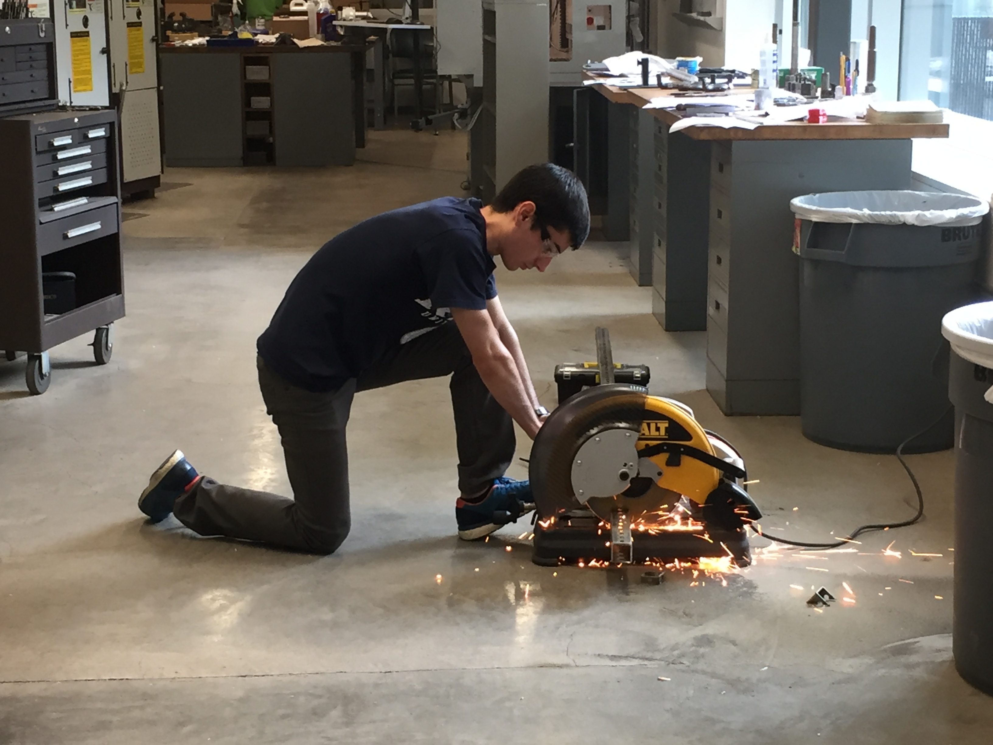
Cutting steel struts for frame of casting stand
Additionally, our casting stand needs an aluminum connector piece between the vertical armrest supports and the dolly wheels. Since there was no better way to connect the struts to the dolly wheels, Jeremy helped us machine a piece that would connect those two parts. Jeremy did a great job using the lathe and vertical mill to create arguably the most beautiful piece on our device. Seeing Jeremy use the lathe is almost like watching an episode of “How It’s Made”. It’s amazing how a cylinder of aluminum can be shaped into a complex piece using a lathe, a mill, and a 2D drawing of the part with dimensions.
From all the work this summer, I have really gained much knowledge in SolidWorks. After creating the entire assembly of the casting stand, I had to create drawings for our team so that when we machined the parts and welded them together, we knew exactly how each piece is cut and where each piece should go. On Wednesday, I created many 2D drawings with the important dimensions of the casting stand components so that our team would be prepared when we were ready to weld.
As we were waiting for our final strut and foam to arrive in the mail, we continued planning the last cuts needs to be made and where each piece would be welded. Luckily, the final strut and foam came just in time, and we were able to cut the tubing and bring it to the welding room in Ryon lab to begin welding. I am very fortunate to have Jeremy as our TA. He is knowledgeable on all the equipment, and he came to Ryon lab with us to make the welds. After several hours of welding, we were able to finish the structure of the main frame of our casting stand. Of course, since all the connections of the square tubing frame were done, we put our device together to do some basic testing to see if our design works. While there are still many issues to be addressed in the coming days, I am overjoyed to see the design I have been working on for the past weeks be successful in standing by itself and being able to support the weight of a person.

Frame of steel struts after welding
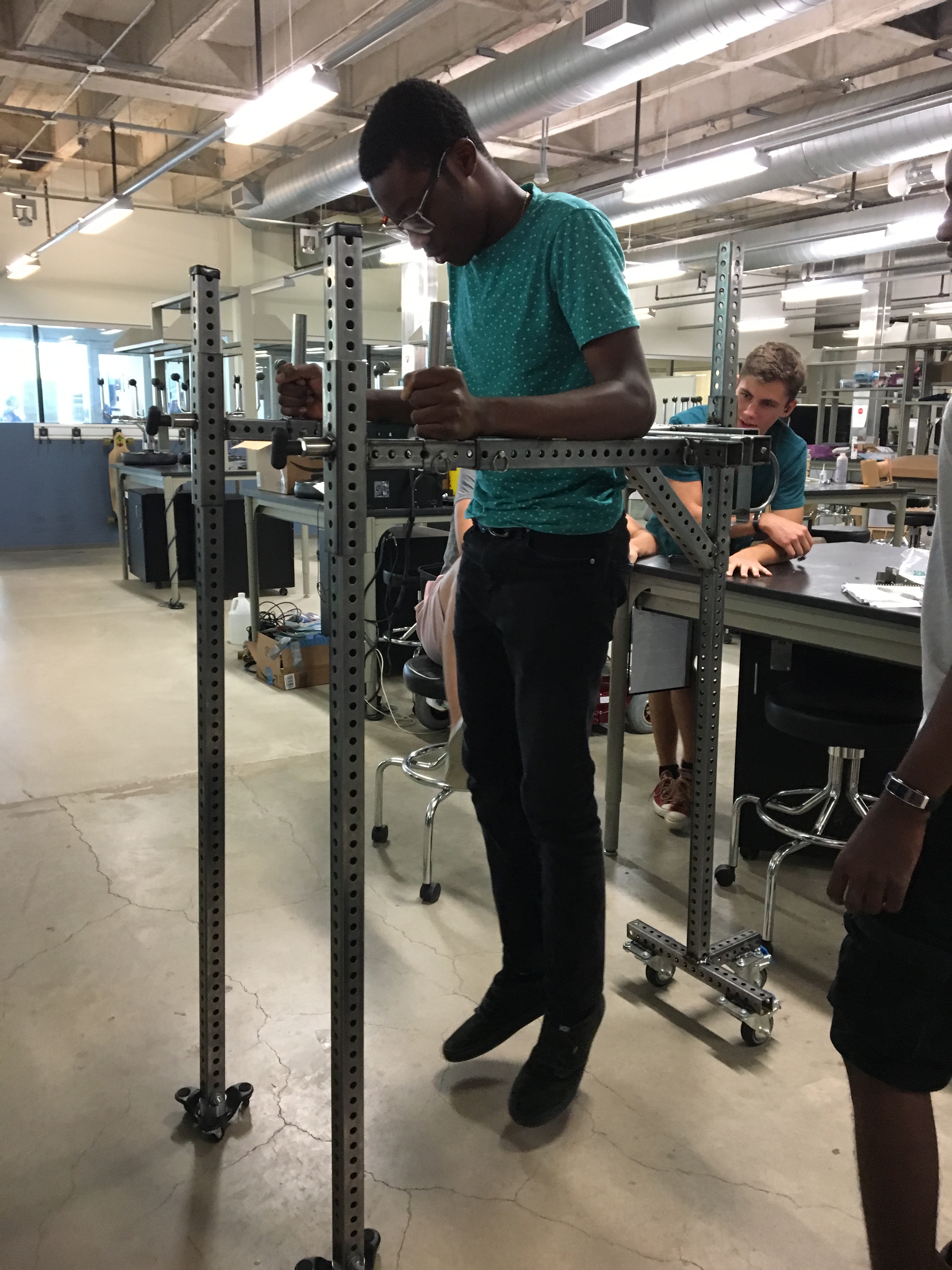
Kelvin supporting all his weight on the casting stand
You have made excellent progress and communicated very clearly and fully your work and positive thoughts about what you learned .